
- Видео 209
- Просмотров 1 408 059
Aaron Danner
Сингапур
Добавлен 2 дек 2011
Complete Playlists for Learning Electronics
Recommended Viewing Order:
1. Circuits For Beginners [FULL CLASS]
2. Electrical Properties of Materials/Semiconductors for Beginners [FULL CLASS]
3. AC & Switching Circuits [FULL CLASS]
4. Motors [HANDS-ON SERIES]
5. Electricity Distribution [FULL CLASS]
6(a). Analog Electronics [FULL CLASS]
6(b). Passive Filters
6(c). Amplifiers and Op-Amps
6(d). Active Filters
6(e). Transistors
6(f). Voltage Regulators
6(g). Feedback in Circuits
6(h). Oscillators
7. Ising Computers [GRADUATE SERIES]
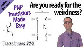
PNP Amplifier Examples (21-Transistors)
PNP examples with full gain derivation. How to combine NPN and PNP transistors to reduce component count in multistage amplifiers. How to calculate the gain in common collector, common emitter, and common base PNP amplifiers.
Aaron Danner is a professor in the Department of Electrical and Computer Engineering at the National University of Singapore.
danner.group
Video filmed and edited with help of CIT, NUS.
Aaron Danner is a professor in the Department of Electrical and Computer Engineering at the National University of Singapore.
danner.group
Video filmed and edited with help of CIT, NUS.
Просмотров: 4 093
Видео

Introduction to PNP transistors (20-Transistors)
Просмотров 50 тыс.Месяц назад
How to bias a PNP transistor. How to deal with negative voltages. How to tell if it's in the forward active mode, saturation, reverse active mode, or cut-off. This is the easy way to handle PNP transistors. Aaron Danner is a professor in the Department of Electrical and Computer Engineering at the National University of Singapore. danner.group Video filmed and edited with help of CIT, NUS.

Load Line Method with Transistors (19-Transistors)
Просмотров 2,4 тыс.Месяц назад
If the emitter is grounded, the transistor has a nonlinear transfer function. How can you determine the gain? Let's use the load line method to find the operating point and then show what happens for both DC and AC. With example problems. Aaron Danner is a professor in the Department of Electrical and Computer Engineering at the National University of Singapore. danner.group Video filmed and ed...

High gain, but not easy to control (18-Transistors)
Просмотров 1,9 тыс.Месяц назад
If we ground the emitter, then a non-linear relationship exists between the output and the input, but we can then see that bipolar transistors have intrinsically high gain. Aaron Danner is a professor in the Department of Electrical and Computer Engineering at the National University of Singapore. danner.group Video filmed and edited with help of CIT, NUS.

Cascode Amplifiers (17-Transistors)
Просмотров 3,9 тыс.Месяц назад
All about cascode amplifiers for the bipolar transistor. Derivation of the gain using the small signal model and by inspection. Explanation of the high frequency performance. Everything is derived and explained from first principles. How does the cascode amplifier avoid the Miller effect? Aaron Danner is a professor in the Department of Electrical and Computer Engineering at the National Univer...

Miller Effect (16-Transistors)
Просмотров 7 тыс.Месяц назад
Parasitic capacitances are worse when you have inverting amplifiers. For example, the common emitter configuration will have reduced performance at high frequencies than other transistor configurations. Why is that? That's what this video is about. Aaron Danner is a professor in the Department of Electrical and Computer Engineering at the National University of Singapore. danner.group Video fil...

Common Base Amplifiers (15-Transistors)
Просмотров 2,5 тыс.Месяц назад
Derivation of the gain from the small-signal model. Let's then derive the gain using inspection and impedance reflection. What is the gain of a common base amplifier? Why would you want to use it? Why is the gain non-inverting? Aaron Danner is a professor in the Department of Electrical and Computer Engineering at the National University of Singapore. danner.group Video filmed and edited with h...

All About Common Emitter Amplifiers (14-Transistors)
Просмотров 1,8 тыс.2 месяца назад
Start with the small signal model of a common emitter amplifier and derive a full and complete expression for the gain. Then, we will do it by inspection using impedance reflection. Then, let's work some example problems. Aaron Danner is a professor in the Department of Electrical and Computer Engineering at the National University of Singapore. danner.group Video filmed and edited with help of...

All About Common Collector Amplifiers (13-Transistors)
Просмотров 1,7 тыс.2 месяца назад
Start with the small signal model of a common collector amplifier and derive a full and complete expression for the gain. Then, we will do it by inspection using impedance reflection. Then, let's work some example problems. Aaron Danner is a professor in the Department of Electrical and Computer Engineering at the National University of Singapore. danner.group Video filmed and edited with help ...
Common Emitter Examples (12-Transistors)
Просмотров 2,5 тыс.2 месяца назад
Full gain calculation in common emitter amplifier circuits. How to design any desired gain from common emitter stages. Full derivations and analysis. Aaron Danner is a professor in the Department of Electrical and Computer Engineering at the National University of Singapore. danner.group Video filmed and edited with help of CIT, NUS.
Design a Phase Shift Oscillator (4 - Oscillators)
Просмотров 1,7 тыс.2 месяца назад
Let's design a phase shift oscillator. Full circuit analysis with discussion. Aaron Danner is a professor in the Department of Electrical and Computer Engineering at the National University of Singapore. danner.group Video filmed and edited by Cheryl Lim. @randomcheryl
Impedance Reflection (11-Transistors)
Просмотров 10 тыс.2 месяца назад
How do you find the impedance looking into the base (or the emitter) of a bipolar transistor? Let's work some examples using the technique of impedance reflection. Aaron Danner is a professor in the Department of Electrical and Computer Engineering at the National University of Singapore. danner.group Video filmed and edited with help of CIT, NUS.
Common Emitter Gain Basics (10-Transistors)
Просмотров 4 тыс.2 месяца назад
Derive the simple gain in a common emitter amplifier without adding too much complexity. Let's work some examples. Aaron Danner is a professor in the Department of Electrical and Computer Engineering at the National University of Singapore. danner.group Video filmed and edited with help of CIT, NUS.
Welcome to The Future
Просмотров 3,6 тыс.5 месяцев назад
Aaron Danner is a professor in the Department of Electrical and Computer Engineering at the National University of Singapore. danner.group NUS professor speaking all four official languages of Singapore: English, Mandarin Chinese, Malay, and Tamil. Tour of the Photonics Lab, Cleanroom, and Centre for Teaching, Learning, and Technology at the National University of Singapore.
Gain in a common collector amplifier (9-Transistors)
Просмотров 3,1 тыс.5 месяцев назад
Let's derive the gain in a common collector amplifier. The gain is usually 1, so the common collector amplifier is used as a buffer. Let's do a full derivation with examples. Aaron Danner is a professor in the Department of Electrical and Computer Engineering at the National University of Singapore. danner.group Video filmed and edited by Cheryl Lim. @randomcheryl
Transistor Biasing: How to combine AC and DC signals in amplifiers (8-Transistors)
Просмотров 3,9 тыс.5 месяцев назад
Transistor Biasing: How to combine AC and DC signals in amplifiers (8-Transistors)
Example Problems: Identify the mode (7-Transistors)
Просмотров 3,2 тыс.5 месяцев назад
Example Problems: Identify the mode (7-Transistors)
Modes of a bipolar transistor (6-Transistors)
Просмотров 3,8 тыс.6 месяцев назад
Modes of a bipolar transistor (6-Transistors)
Why can you treat a power supply like an AC ground? (5-Transistors)
Просмотров 2,9 тыс.6 месяцев назад
Why can you treat a power supply like an AC ground? (5-Transistors)
Simple bipolar circuits: Cut-off and beta (4-Transistors)
Просмотров 2,9 тыс.6 месяцев назад
Simple bipolar circuits: Cut-off and beta (4-Transistors)
When to use a common collector amplifier (3-Transistors)
Просмотров 5 тыс.6 месяцев назад
When to use a common collector amplifier (3-Transistors)
Designing Passive Butterworth Filters (10 - Passive Filters)
Просмотров 2,7 тыс.6 месяцев назад
Designing Passive Butterworth Filters (10 - Passive Filters)
Transistor amplifier configurations (2-Transistors)
Просмотров 6 тыс.6 месяцев назад
Transistor amplifier configurations (2-Transistors)
Transistors for Beginners (1-Transistors)
Просмотров 6 тыс.6 месяцев назад
Transistors for Beginners (1-Transistors)
Voltage regulator short circuit protection (7 - Regulators)
Просмотров 11 тыс.7 месяцев назад
Voltage regulator short circuit protection (7 - Regulators)
Voltage regulator with negative feedback (5 - Regulators)
Просмотров 3,2 тыс.7 месяцев назад
Voltage regulator with negative feedback (5 - Regulators)
Fully Explained Voltage Regulator Designs (6 - Regulators)
Просмотров 3,7 тыс.7 месяцев назад
Fully Explained Voltage Regulator Designs (6 - Regulators)
Series Voltage Regulator (4 - Regulators)
Просмотров 7 тыс.7 месяцев назад
Series Voltage Regulator (4 - Regulators)
Line and load regulation (3 - Regulators)
Просмотров 2,8 тыс.7 месяцев назад
Line and load regulation (3 - Regulators)
How to use a zener diode (2 - Regulators)
Просмотров 3,1 тыс.7 месяцев назад
How to use a zener diode (2 - Regulators)
😢can I any one tell how I set the frequency from function generator
What’s the negative side of Delta not having a neutral? Symptoms? Thanks, Austin
These videos are pure gold! So much better than any tutorials I've read on the matter 🥇
What if the load for the both voltage sources is the same i.e 10 ohms. Surely the load is not fixed
The values from the table. Where can you find it? Any book you recommend ?
OK, so I ran across a really old 2-phase motor and was working on a replacement. I put an amp meter on the 2 phases I found at the disconnect and took a voltage reading too. I wanted to calculate total motor power to see if the current motor is sized correctly for the load. I put them into a spreadsheet to calc power. However, that spreadsheet used P = V * I * sqft(3). I think that for a 2-phase system that was wrong. Would I actually just add the amps from the 2 wires together to get the power? As is P = V * (Amps1 + Amps2)
Love the clear explaination, helped to clear up a lot on the topic. Thanks!
Very good video: short and to the point, well-dictated, examples given. Great job
very good
I'm here for eDX courses and i love the way you explain.
something doesnt seem right. he says you have to overcome the work function in order to get electrons to flow, but, if you think about it, a magnet moved across a wire gets electrons to move, meaning, the power supply already overcomes the work function in order to get current to flow and since the vacuum gap is essentially a conductor with zero resistance, the electrons should continue to flow, so his reason for why it doenst unless additional means of essentially induction occur seems irrational. replace the vacuum gap with a conductor and current flows, so why doesnt current flow when a gap of a conductor is replaced with a zero resistance conductor? hes talking like there is an insulator between the electrodes which require a sufficient voltage to overcome to induce current flow, which would mean a vacuum isnt actually empty
another great video and explanation, thanks!
Aaron's BJT videos are great. It takes him 25 minutes to explain various topics, I spend hours offline to understand the contents. After putting that offline effort in, I watch the video again.
Thanks Aaron
Very nice presentation
Why is ((V2/V1)(V1/V2)) = 1 is needed? I need the thoery behind this equation... All the analysis is very clear.. But At 3:28 You just jumped to derivation by saying my " strategy is just to multply this two term... " and am lost there🙏🏾🙏🏾🙏🏾
thanku aaron
transistors are diode over a layer of n or p channel material. if diode conducts transistor will be open. its simple.
I am back and starting here maybe this will help me in understanding motor control transistors, Look like a 3 year course ahead. Dennis
Thank Dr Danner, I was a Mech Engr and worked is systems, Medical Imaging, Factory Automation, Robotics Assembly etc etc. In retirement i have pulled out my old (1950) train set. I was determined to update it using IOT, why not that should be fun. Oh my, Motor control with Transistors is giving me such headaches. I buy circuits that work but I have no idea why. And when I want to tweak the performance I am lost at which way to go. I tried to listen and learn but I must say it is very hard. Do you have any practical applications of motor control with braking? I have a mini DC motor 3.5VDC that i want to make Puff Smoke on the engine stack. Timed to the drive wheel rotation. So I need a burst then stop, then burst then drop. The burst is driven by a sensor, but the Brake was design to stop the motor when the puff trigger pulse is off. But I am getting so much coasting there was no stop of smoke between puffs. Its a very simple and the circuit i was given is very simple but now I need to tweak the circuit. ??????????? No idea where to go to decrease or increase volts. The originator suggested dropping one resisitor from 500 to 100 ohms, and it helped. Amazing, No I am looking at the fan blade weight. It this anything you would have information of a link to a lecture that might help me to get this logic sunk into my grey cells. Thank You, Dennis
how can we make that circuit without the voltage regulator(as a standalone overcurrent/short circuit protection)? thanks
This is absolute legendary explanation. From my experience transistors have always been a very confusing topic considering so many variables and assumptions. Your videos are a treasure chest for this matter
No comments interesting
I'm here
@@naskun0441 great this a good piece in my opinion
@@madscientist3193 But the problem, how to solve it :/
I love Ben Eater, but this guy is the best at teaching this content. I am new to his community and I hope he is still making content. Excellent work brother.
Very informative playlists on your page! I think there is a correction in example 1. The base current is 4.3mA/100 = 0.043 mA and not 0.0043 mA. About 1%. Still negligible. 👍🏼
Excellent explanation, & easy to understand! Now, I understand that Ge transistors have about 0.2 volts across their junctions and Si have about 0.6 volts. But I have here in my hands a power transistor (?, they look just like b/b diodes to a diode check meter) that doesn't fit into either slot very well with 0.48 and 0.49 volts. It's a Motorola SJ4836, a TO-3 from 1985. I can't find any documentation on it, and don't know even if it's a Si transistor with that low a drop, and just a little high to be Schottky. Any idea as to what this junk box find might be?
Great series so far. Just a comment, it was a bit confusing when you said "this is not a source", while drawing the symbol for a source at 9:06.
awesome
You went too fast ! Why ?
After designing a filter with a certain fb, I would like to change fb by only adjusting the resistance value. Is there any other way to do this than to change the values of the resistors that make up the filter one by one? I would like to change the center frequency by changing the value for the number of minimum resistors.
Which unit has the calculated gain? If it is not dB, how can we convert it to dB?
god's work
Fantastic!
At 9:26 in this video: When calculating Re (emitter resistance), where does the value 26 come from? Is that a static constant? I can't place it. Thanks!
It's k*T/q at room temperature, so it's almost a constant.
You could have explained all the cases by superimposing the vcc= rc x ic + vce curve on the transistors operating curve of the manufacturer instead of drawing on for 20 minutes and no doubts cleared
Can you tell one thing? Give typical voltages on the ic vs Vce curve. There is a sharply rising part initially and then plateaus of. Where is 0.7 volts on this curve- at the origin before it takes off or where it plateaus off? , for a given Ib. Everybody takes 0.7 volts without getting into the saturation aspect. Secondly in the first example of forward bias case the Ve and Ib will remain the same even if you took Rc and Re as 10k instead of 1k. Is that believable? In the 1k case the operating ppint will be on the plateau region ie saturated. In the 10k case the operating curve will cut the Ic curve on the vertical stretch meaning Vce in the vicinity of 0.7 and possibly several volts in the 1k case
i have found in practice and documentation that Cbc X Beta is quite close in approximating Miller capacitance. it's not exact, but close enough for most design work.
Thank you so much for these videos! I knew all this stuff 40-plus years ago, when I got my AAS in electronics, but have forgotten most of it. Your efforts here are very much appreciated!
Very good. I wish we had vids in the '70s (in the USN) & early '80s -- when I was in EE school. Good luck.
Thanks
thank you for the explaination . 👍👍👍👍
Nevermind I found it. :) Great videos. Edit: I found this map but I can't see where it shows substations. atlas.eia.gov/apps/895faaf79d744f2ab3b72f8bd5778e68/explore
I am thinking how to make it more stable... it is ok but still not enough for me.
This is where circuit analysis enters the time domain. Also energy storage in the form of an electric field (via capacitor) and magnetic field (via inductor). Time domain analysis is usually introduced via switching events in resistive circuits with dc sources that also have capacitors and inductors.
I suspect people get confused if they try to reconcile transistor action (involves including the effects of doped silicon) with the sign convention for current in the circuit which is opposite the sense of electron mobile charge carrier flow.
Professor, I have found your videos to be nothing short of amazing. I feel like I’ve retained so much more than when I read the same content in a textbook. Any chance you will also teach us FETs and Power Amplifiers? Crossing my fingers that you will!
Thank you, that's very kind. Those topics are indeed in preparation now.
On page 36 of the book "The Art of Electronics 3rd Edition", Figure 1.72 shows a simple diode voltage clamp which looks cool, so I gave it a try. I set the cathode of the diode to a commercial DC voltage supply, set its output to 0v. Signal is connected to my signal generator, it generates a sine wave at 5v / -5v peak. In my imagination, the diode anode should be around 0.7v peak. To my surprise, no, no, the output waveform showing on oscilloscope show the output being clamped, but not at 0.7v, it was as high as 1.85v... What's going on? The voltage output showing on power supply panel is 0v, but the actual value is 1.85v. Obviously, this voltage source is far away from an ideal voltage source, it has a big internal impedence. By inserting an op amp voltage follower between the voltage supply output and the diode cathode, the problem went away. Now, the output wave has 0.7v peak value.
I was very intrigued by reverse active mode operation and went on a small googling tangent. Results came up with this very specific usecase for reverse-active-mode: Fuzz-Effects for Guitars. Running VERY HIGH gain NPN Transistor (2n5089 e.g., with a whopping 1.2k in the best case) in reverse mode severely limits their gain and reduces saturation current such that the transistor itself saturates and distorts the input signal long before clipping into the supply rails. This is said to give a more "tube-like" distortion with less unpleasant harmonics.
Thanks for the amazing and clear content, subscription earned!
great video as always